Book a Consultation
Classifications and Credentials:


Track Geometry Explained: Gauge, Alignment, Cross-Level, and Warp
If a train has ever felt rougher than usual over a certain stretch of track, the cause often traces back to track geometry, the set of measurements that describe how the rails sit in relation to each other and the roadbed. Every rail system, whether it moves passengers, freight, or product between plant and mainline, depends on these measurements staying within tolerance. This article walks through the four core measurements, gauge, alignment, cross-level, and warp, and explains why each one matters for derailment prevention and FRA compliance.
Why Track Geometry Determines Derailment Risk and FRA Compliance
Track geometry refers collectively to the four measurable parameters, gauge, alignment, cross-level, and warp, that describe how rails are positioned relative to each other and to the roadbed beneath them. Each parameter answers a different question. Gauge asks whether the rails are the correct distance apart. Alignment asks whether the rail follows its intended straight or curved path. Cross-level asks whether the two rails sit at the correct relative height. Warp asks how quickly that height relationship is changing over a short distance. Together, they tell an inspector or owner whether a section of track can safely carry the loads and speeds it was designed for.
The Federal Railroad Administration sets allowable geometry deviations under 49 CFR Part 213, and as of 2026 those tolerances tighten as track class rises. A branch line rated for 10 mph freight movement has more forgiving thresholds than a mainline segment cleared for higher speeds, which means the acceptable range for gauge widening, alignment deviation, and cross-level difference depends directly on how fast trains are permitted to run over that track. For facility owners, this creates a practical link between operating speed and maintenance obligation: raising a speed limit without addressing geometry first is not an option under the standards.
We think of these four measurements as the vocabulary that ties an inspection report to an actual maintenance decision. Knowing that a defect is a gauge issue rather than an alignment issue changes what a repair crew does on site. If you want the broader picture of how geometry defects fit alongside rail wear, fastener failure, and other causes of derailment, our derailment causes article covers those failure modes in more depth. This piece stays focused on defining the measurements themselves.
Gauge: The Distance Between Rail Heads
Gauge is the distance between the gauge faces of the two rail heads, the inner surfaces that a wheel’s flange rides against. In the United States, standard gauge is set at 4 feet 8.5 inches. That number is fixed by design, but the actual distance between rails on a given piece of track can drift from that figure as ties, fasteners, and ballast age.
Railroad gauge measurement is taken at a fixed point below the top of the rail, typically about 5/8 inch down from the running surface, using either a gauge bar during a walking inspection or the sensors on a track geometry car for continuous readings over long stretches. This is a deliberate, repeatable measurement point, not a visual estimate of rail spacing. A gauge bar gives an inspector an instant reading at a single location, while a geometry car produces a continuous data trace that shows exactly where gauge starts to drift before it becomes a flagged defect.
Gauge almost never fails on its own. Widening gauge is usually a symptom of something happening underneath the rail, deteriorating ties that no longer hold spikes or screws firmly, loose or worn fasteners, or plate cutting where the tie plate has worn a groove into the tie itself. Left unaddressed, wide gauge lets the wheel flange lose its guiding contact with the rail, and in the worst case a wheel can drop between the rails entirely. Because gauge issues trace back to the ties and fasteners holding the rail in position, the fix is rarely a gauge adjustment alone. It usually involves tie replacement or fastener renewal, which restores the structural support that was keeping gauge correct in the first place.
Alignment and Common Track Alignment Defects
Alignment describes the lateral position of the rail compared to a true reference line, whether that reference is a straight tangent section or the designed curve of a bend in the track. An inspector or a geometry car compares the rail’s actual position at each point against where it should be, and any lateral deviation from that reference line is recorded as an alignment reading.
Track alignment defects generally fall into two patterns. The first is a long, gradual deviation, sometimes called line-and-surface drift, where the rail slowly bows away from its intended path over many feet, often on curves or long tangents where ballast has shifted or settled unevenly. The second is a short, sharp kink, a localized dip or bulge caused by a failed tie, a soft spot in the subgrade, or a washout beneath the ballast. Both patterns get flagged under FRA alignment tolerances, but they call for different repairs: gradual drift often responds to surfacing and realignment work across a longer section, while a sharp kink usually points to a specific failed component that needs targeted replacement.
Alignment matters on tangent track just as much as it does on curves, which is a common point of confusion for owners who assume lateral deviation is only a curve problem. On straight track, poor alignment increases lateral wheel forces and can contribute to a rough, swaying ride known as hunting oscillation. On curves, poor alignment compounds with centrifugal force and can contribute to wheel climb, one of the mechanisms we cover in more detail in our article on what causes train derailments. In both cases, alignment defects tend to worsen under repeated traffic loading if they are not corrected early, which is why they are one of the first things a geometry car flags for a maintenance crew to walk out and confirm.
Cross-Level and Warp: Reading the Relationship Between the Two Rails
Cross-level is the difference in elevation between the two rails measured at a single point along the track. On tangent track, the two rails should generally sit at the same height, so any measurable difference is a cross-level defect. On curves, the outer rail is intentionally raised above the inner rail by a designed amount called superelevation, which helps offset the centrifugal force acting on a train as it moves through the curve. In that case, cross-level is not measuring an error, it is confirming that the designed elevation difference is actually present and within tolerance.
Warp is a different measurement entirely, though it is closely related. Warp is the rate of change in cross-level over a set distance, essentially a measure of how quickly the track is twisting from one point to the next. A single cross-level reading tells you the elevation difference at one spot, but it cannot tell you whether that difference is stable or changing rapidly a few feet away. Warp fills that gap by comparing cross-level readings at two points a defined distance apart, which is why cross level and warp are always discussed as a pair rather than as interchangeable terms. Confusing the two is a common mistake: a track segment can have a perfectly acceptable cross-level reading at every individual point and still have a dangerous warp defect if those readings are changing too fast between points.
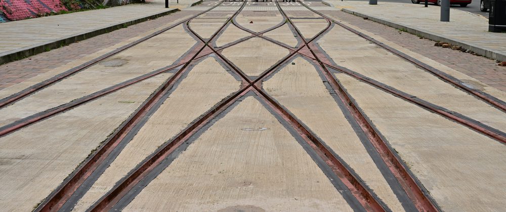
Excessive warp matters because a twisting section of track can unload one wheel of a truck enough that it loses effective contact with the rail, which raises the risk of that wheel lifting or climbing. This risk shows up with particular frequency through switches, diamonds, and other special trackwork, where multiple rail transitions happen close together and small construction or maintenance tolerances stack up quickly. A facility running frequent moves over a turnout or crossing should expect that area to receive closer geometry scrutiny than a long stretch of open tangent track, precisely because warp tends to concentrate at these transition points.
How We Monitor and Correct Geometry Before It Becomes a Safety Issue
Geometry gets checked through two complementary methods. Manual gauge and level tools, used during routine walking inspections, give an inspector a direct reading at a specific location and are well suited to smaller yards, spurs, and facility trackage where a crew can walk the full length in a reasonable time. On larger systems, dedicated track geometry cars run over the rail at or near operating speed and record continuous data on gauge, alignment, cross-level, and warp simultaneously, producing a full trace of the line rather than a series of spot checks.
When a reading falls outside tolerance, the correction depends on which parameter is off and why. Tamping and surfacing work restores proper cross-level by compacting ballast under the low rail and bringing the track back to its designed elevation profile. Tie replacement addresses situations where worn or rotted ties have lost their grip on fasteners, which is often the root cause behind both gauge widening and cross-level drift. Rail adjustment, including gauge-side repairs and realignment of the running rail itself, brings gauge and alignment readings back within the allowable range. We cover the mechanics of this work in more detail on our Track Maintenance page.
How often these checks need to happen depends on traffic volume and the track class assigned to that segment under FRA standards. A facility running a handful of moves a week can generally work from a longer inspection interval than a line seeing daily heavy traffic. We walk through how to set that schedule in our guide on how often railroad tracks should be inspected for FRA safety compliance, and our Track Inspection Services team can help build an inspection plan that matches your traffic pattern rather than a generic default.
Putting the Four Measurements to Work on Your System
Understanding gauge, alignment, cross-level, and warp gives rail owners a shared vocabulary with their maintenance crews and inspectors, so a defect report reads as a specific, actionable problem rather than a vague warning. That shared language matters most when decisions have to move quickly, whether that means confirming a speed restriction is warranted or scoping a repair before the next scheduled inspection. If any of these measurements on your system are drifting out of tolerance, or if you simply want a clearer read on where your track stands today, we invite you to reach out. Visit our home page at tracktechinc.com to see the full range of what we do, or Learn more about our services to start a conversation about an inspection and maintenance plan built around your track class and traffic.