Book a Consultation
Classifications and Credentials:


What Is a Railroad Turnout and How Is It Installed?
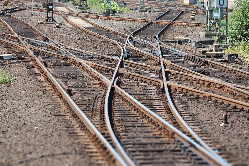
Rail networks are only as flexible as their infrastructure allows. A single unbroken track can move a train in one direction, but the moment you need to route cars to a siding, connect an industrial spur, or let two trains share a corridor, you need a way to guide rolling stock from one track to another. That mechanism is the railroad turnout, and it sits at the heart of virtually every functional rail operation.
We work with railroad operators, industrial facility managers, and transportation companies across Kentucky, Illinois, and Tennessee, and turnout questions come up constantly: what operators are actually dealing with when a turnout is specified on a project, what installation looks like from the ground up, and how to keep a turnout performing reliably once it’s in service. Here’s the field-level explanation.
The Mechanics Behind Every Track Switch
A railroad turnout is a mechanical assembly that lets a train transition from one track to another without stopping or lifting. It sounds straightforward, but the engineering behind it is precise. Every component in the assembly has a specific role, and they all have to work together in sequence for the move to happen safely.
The assembly begins with the stock rails, the fixed running rails that form the main track through the turnout. Against these fixed rails sit the switch points, sometimes called switch rails or simply “the points.” These are a pair of tapered, movable rails that pivot at one end and close tightly against one stock rail or the other depending on the desired route. When a wheel enters the turnout, the flange rides against the face of whichever point is set, and that contact steers the wheel onto the intended path.
From the points, the wheel travels along the closure rails, the connecting rails that bridge the gap between the switch points and the frog. The frog is the X-shaped casting or fabricated assembly where the two rails physically cross each other. This is where the wheel must transition across the opposing rail, and the geometry of the frog determines how smoothly that crossing happens. The frog has a flangeway cut through it that lets the wheel flange pass without interference, and the angle of that crossing is what defines the frog number.
Controlling all of this is either a switch stand or a switch machine. A switch stand is a manual throw mechanism, typically operated by a crew member on the ground who moves a lever to shift the points from one position to the other. A switch machine is a powered device, either electric or pneumatic, used in automated or remotely controlled applications. In either case, the mechanism moves a switch rod that connects to the points and physically displaces them from one stock rail to the other.
What makes turnout mechanics demanding from a maintenance perspective is that every component in the assembly is load-bearing and takes the full impact of passing trains. The points must close tightly against the stock rail with no gap that a wheel flange could catch. The frog must be properly aligned so the wheel crosses cleanly. The ballast beneath the entire assembly must provide uniform support so no part of the turnout settles unevenly. When any of these conditions drift out of tolerance, derailment risk goes up, which is why precision matters so much in both installation and ongoing maintenance.
Types of Turnouts and When Each One Is Used
Not every railroad turnout is the same, and selecting the right type for a given application is one of the first decisions that shapes a project. The most fundamental variable is the frog number, which describes the angle at which the diverging track branches away from the main track. The frog number is a ratio: a No. 10 frog means the diverging track moves one foot laterally for every ten feet of forward travel. A No. 8 frog is steeper, moving one foot laterally for every eight feet. A No. 20 frog is much more gradual.
The practical consequence of this ratio is speed. Steeper angles, represented by lower frog numbers, require trains to slow well down before entering the diverging route. That suits yard switching operations, where speeds are already low and space is at a premium. Higher frog numbers let trains enter the diverging route faster, which is why mainline turnouts commonly use No. 15, No. 20, or higher. Getting the frog number wrong for the application creates either a speed restriction that disrupts operations or a geometry that’s unsafe for the traffic it carries.
Beyond the standard single turnout, several configurations serve specific operational needs. A crossover connects two parallel tracks, letting trains move laterally from one main track to the other. It’s essentially two turnouts placed back to back with a short connecting track between them. A double crossover places two crossovers in an overlapping arrangement so trains can move in either direction between two parallel tracks, a configuration common in terminal facilities and busy interchange yards.
Curved turnouts come up frequently in industrial facility work. Standard turnout geometry assumes a straight main track through the assembly, but many industrial spurs and tight yard layouts don’t have the straight run a standard turnout requires. A curved turnout is engineered with a curved main track through the assembly, letting the switch fit within a constrained footprint. These take more precise engineering and more careful installation, but they’re often the only practical solution when a facility’s rail layout doesn’t allow for a straight lead.
For industrial facilities and private rail operators in our region, the choice between these configurations usually comes down to the geometry of the site, the speed of operations, and the type of equipment being routed. A coal handling facility with slow-moving cuts of cars has very different needs than a transload terminal where loaded unit trains need to enter a siding at reduced speed. Understanding these distinctions before specifying a turnout saves time and money later in the project.
Planning a Turnout Installation: What Happens Before the First Spike
The quality of a turnout installation is largely determined before any material arrives on site. The planning phase is where the important decisions get made and where errors are cheapest to correct. By the time a crew is setting ties and positioning rail, the window for easy course correction has closed.
A proper site assessment starts with a track geometry survey of the existing track structure where the turnout will be installed. We need to know the existing gauge, the alignment of the track, and the condition of the subgrade beneath the ballast section. If the subgrade is soft or has drainage problems, adding a turnout assembly, which distributes load differently than standard track and requires a more stable foundation, will accelerate any existing problems. Drainage review matters especially in Kentucky, Illinois, and Tennessee, where winter freeze-thaw cycles can cause serious subgrade movement. A turnout installed over a poorly drained subgrade will settle unevenly, leading to gauge widening and point misalignment.
Frog number selection and turnout length are determined during planning based on several variables: the maximum train speed on the main track, the length of the cars or locomotives that will use the diverging route, and the angle needed to reach the diverging track within the available space. A turnout that’s too short for the car lengths in service creates a condition where a long car occupies both the main track and the diverging track at the same time, which disrupts operations and can be unsafe. Getting this geometry right in the planning phase is far less expensive than discovering the problem after installation.
Regulatory compliance also has to be addressed before work begins. FRA regulations under 49 CFR Part 213 govern track geometry standards including turnout geometry, gauge tolerances, and switch point fit. These standards define the allowable wear and misalignment thresholds the installation must meet from day one and that maintenance teams must monitor throughout the turnout’s service life. Any installation on a federally regulated railroad also requires coordination with the operating railroad to obtain proper work windows. No crew should set foot on the right-of-way without a confirmed work window and a qualified flagger or on-track safety officer in place. These aren’t optional steps, and treating them as afterthoughts is how projects get delayed or, worse, how people get hurt.
Our turnout installation process integrates all of this planning work before we mobilize a crew, because we’ve seen what happens when it’s skipped. The engineering phase is an investment that pays for itself many times over in the field.
The Installation Process Step by Step
Once planning is complete and the work window is confirmed, the physical installation begins with the roadbed and ballast section. The existing ballast in the installation zone is excavated or redistributed to create a clean, uniform surface at the correct elevation. If the subgrade needs more work, such as undercutting and replacing fouled ballast or adding drainage improvements, that happens at this stage before any track material is placed.
Turnout ties, also called switch ties, are installed next. These differ from standard track ties in two ways. They’re longer, because the turnout assembly is wider than standard track and the ties need to extend beyond the outer rail on both sides. They’re also more closely spaced, because the turnout assembly distributes load differently and needs more support at the points, the frog, and the closure rail sections. The tie layout follows a predetermined pattern based on the specific assembly being installed, and getting the spacing right is what gives the assembly proper support once it’s set.
The prefabricated turnout assembly is then positioned on the ties. Modern turnout assemblies are typically fabricated off-site to manufacturer specifications and delivered to the job site ready to set. Prefabrication improves quality control and reduces the time the track is out of service. The assembly is positioned, and the connection to the existing track on both the main track end and the diverging track end is made using compromise joints or standard joint bars, depending on the rail section.
After the assembly is set, the gauging, lining, and surfacing work begins. Gauging confirms that the distance between the rails through the entire assembly meets the required tolerance. Lining adjusts the lateral position of the track to match the design alignment. Surfacing brings the track to the correct elevation and cross-level. Ballast tamping packs the ballast tightly beneath the ties to provide the uniform support the assembly requires. The frog alignment and switch point fit are checked against manufacturer tolerances and FRA standards, and any adjustments happen at this stage.
The switch rod and throw mechanism are then connected and adjusted. For a manual switch stand, that means confirming the points move fully from one stock rail to the other with a clean, positive throw and that the stand locks securely in both positions. For an electric switch machine, the electrical connections are made, the machine is calibrated, and the end-of-stroke positions are confirmed. The machine must move the points completely and lock them in position before the circuit closes, which is how the system confirms to a train crew or dispatcher that the switch is properly set.
The final phase is slow-order testing. The switch is operated repeatedly to confirm consistent performance, and a test move is made at restricted speed with actual equipment before the turnout is released for normal service. That test move is the last line of defense before revenue traffic uses the new installation, and we don’t skip it regardless of schedule pressure.
Keeping Turnouts in Service: Maintenance Priorities
A well-installed turnout isn’t a set-and-forget piece of infrastructure. The components that work hardest wear the fastest, and catching wear early is the difference between a scheduled repair and an emergency derailment response. The two components that demand the most attention are the switch points and the frog.
Switch points wear in two ways. The contact face of the point, where the wheel flange bears against it during a move, wears laterally over time. The point can also develop a vertical lip or batter from repeated wheel impacts. Either condition creates a scenario where the wheel flange can climb the point rather than being guided by it, a direct derailment risk. Point grinding can restore the correct profile in the early stages of wear, but eventually the point reaches a condition where replacement is the only safe option. Regular track maintenance inspections that include a close look at point condition let operators plan point replacements on a schedule instead of reacting to a failure.
The frog wears where wheels cross the opposing rail, an area called the point of frog. This is the highest-impact zone in the entire assembly, and it’s where metal loss happens fastest. Manganese steel frogs are preferred in higher-traffic applications because manganese work-hardens under repeated wheel impact, which extends service life compared to standard carbon steel. When a manganese frog wears beyond acceptable limits, the worn area can often be built up with weld and reground to restore the correct profile. When weld repair is no longer practical, a manganese insert replacement or a full frog replacement becomes necessary.
Ballast condition beneath the turnout is easy to overlook until it becomes a serious problem. Fouled ballast, which has accumulated fine material from tie wear, coal dust, or other sources, loses its ability to drain and provide uniform support. Uneven settlement beneath a turnout leads to gauge widening and point misalignment, both FRA-reportable defects. Periodic ballast cleaning or replacement beneath turnouts, particularly in areas with heavy traffic or hard seasonal freeze-thaw cycles, is a cost-effective way to prevent these problems.
Automation plays a growing role in turnout maintenance programs. Electric switch machines allow remote monitoring of switch position, so a dispatcher or maintenance supervisor can confirm a switch has thrown completely without sending someone to physically inspect it. More advanced systems detect abnormal current draw or throw time, early indicators of a mechanical problem developing in the machine or the points. These capabilities support predictive maintenance and reduce the manual inspection burden on crews. Our railroad automation solutions integrate this monitoring into existing rail operations, giving operators better visibility into the condition of their switches without adding to their labor requirements.
Why the Full Scope Belongs With One Contractor
Every stage of a turnout’s life is connected to the stages before and after it. The frog number chosen during planning sets the speed capability of the installation. The subgrade work done before the ties are set determines how long the turnout holds its geometry. The precision of the gauging and lining determines how the switch performs from the first test move, and the maintenance program that follows determines how long the turnout stays in safe, productive service.
Cutting corners at any one stage creates compounding problems: a turnout on a poorly prepared subgrade demands constant maintenance attention, the wrong frog number either restricts train speeds or creates a condition the track structure can’t safely handle, and an uninspected turnout develops point or frog wear that goes undetected until it becomes a safety issue.
Working with a contractor who handles the full scope, from engineering and planning through installation and long-term maintenance, closes the gaps that appear when multiple vendors split phases of the same project. When the team that planned the installation also maintains the turnout, they know exactly what was built and what to look for as the assembly ages.
At Track Tech Inc., we’ve been doing this work since 1980, and our experience across Kentucky, Illinois, and Tennessee covers everything from industrial facility spurs to mainline turnout installations. If you’re planning a new turnout, evaluating a switch that isn’t performing correctly, or putting a maintenance program in place for your existing rail infrastructure, reach out to our team to discuss your project. We can also help with related needs including track inspection, tie replacement, and on-track safety coordination, so you have one experienced partner for the full scope of your rail work.